|
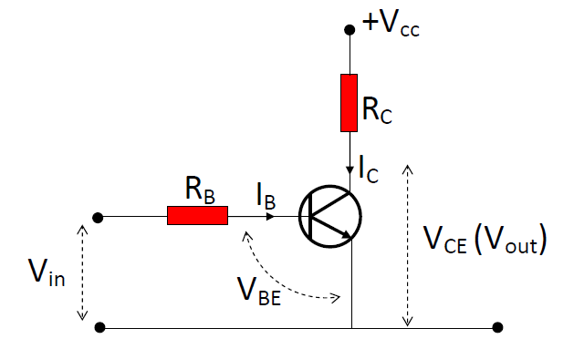
- Characteristics of the (ideal) NPN transistor:
- When VBE < 0.7V, IB= 0; when IB ≠ 0, VBE is always equal to 0.7V.
- Before saturation, IC = βIB, where β is the current gain of the transistor.
- IC is saturated when VCE is dropped to zero.
- Voltage Relationships:
- Input : Vin = IBRB + VBE
- Output: VCE + ICRC = VCC
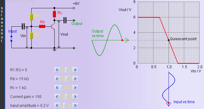
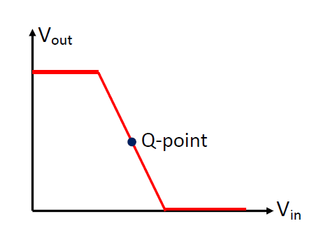
- Quiescent Point (Q-point)
Before an input signal is fed into the amplifier, a steady base current flows
into the transistor to cause a steady Vout. When a time-varying input
signal is added to this steady input, the useful output will then fluctuate about
the steady output (the Q-point). An optimal Q-point is chosen at the mid-way of
the linear sloping part of the Vout - Vin graph in order to
maximize the input amplitude that can be amplified with no distortion.
- Capacitors
The two capacitors in the circuit are called “d.c. blocking capacitors”.
They are used to prevent currents from flowing into the input device (e.g. microphone)
and the output device (e.g. earphone)
|
|