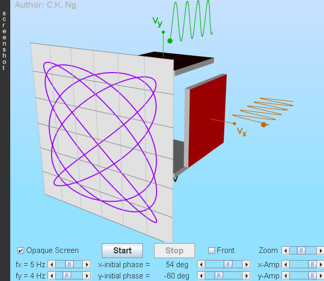
Lissajous Figures
- Drag to change the angle of viewing.
- Sinusoidal voltages are applied to the horizontal and vertical deflection plates, they have the form V = A sin(ω t + φ), where A is the amplitude, ω is the angular frequency and φ is the initial phase.
- Deflection plate is red (black) when it is positive (negative).
- The screen is viewed directly from the front when the box "Front" is checked. Click a point on the screen will show the coordinates of that point.
- The Lissajous figures shown elsewhere may look different to those generated here (by specifying the same frequency ratio and initial phases). Most probably the cosine function is used instead.
|
Run outside of the browser by pressing 'Enter' or double-clicking the Jar file |
(I) Finding frequency ratio and phase difference (φ) from Lissajous figures |
||
(a) 0o, 90o, 180o(Amp = Amplitude; assume same voltage sensitivity) |
||
.png)
φ = 0o |
.png)
φ = 180o |
|
| ||
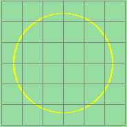
φ = 90o |
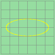
φ = 90o |
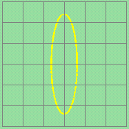
φ = 90o |
| ||
(b) General Case | ||
1.png)
|
2.png)
|
|
|
|
||
1.png)
|
2.png)
|
|
|
|
||
|
We do not know whether x leads y or y leads x unless the sense of rotation is known. Clockwise rotation: y leads x; counterclockwise rotation: x leads y. |
||
(II) Frequencies are different, but in a simple ratio |
||
|
The pattern generally depends on x- and y-frequency and their initial phases. The ratio of the two frequencies can be found easily by the following method: |
||
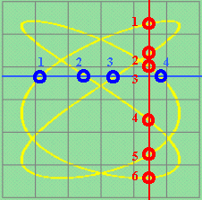 |
Draw a vertical and a horizontal line to cut the pattern curve, but avoid passing through any self-intersection
points of the pattern curve. Count the number of intersection points of the vertical line with the pattern curve. Let this number be m. As well, count the number of intersection points of the horizontal line with the pattern curve. Let this number be n.
Hence, x-frequency : y-frequency = m : n. |
|
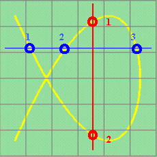 |
One more example, x-frequency : y-frequency = 2 : 3 |
|
